Determination of Young's Modulus
by Bending of Beam Method
A polished interactive lab workspace covering theory, apparatus, procedure, simulation, observations, and result analysis for this undergraduate experiment.
Objective
Section 01Aim
To determine the Young's modulus of the material of a rectangular beam by measuring its deflection under known loads.
Learning Objectives
After completing this experiment, students will be able to:
- Understand the concept of Young's modulus as a measure of the stiffness of a material.
- Explain the principle of bending of a simply supported beam under a centrally applied load.
- Assemble and align the experimental setup using two knife-edge supports.
- Measure the central deflection of the beam accurately for different applied loads.
- Determine the Young's modulus of the beam material using experimental observations and the relevant formula.
- Analyze the relationship between applied load and beam deflection within the elastic limit.
- Estimate experimental uncertainties and identify possible sources of error.
- Relate the experimental findings to practical applications in engineering, construction, and material design.
After completing this virtual experiment, learners will be able to:
- Understand the concept of Young's modulus and its significance in characterizing the elastic properties of materials.
- Explain the principle of bending of a simply supported beam subjected to a central load.
- Explore the effect of applied load and beam dimensions on the central deflection using an interactive simulation.
- Observe and analyze the relationship between load and deflection within the elastic limit.
- Determine the Young's modulus of the beam material from simulated experimental data using the appropriate formula.
- Interpret experimental observations through tables, graphs, and calculations generated during the simulation.
- Evaluate the influence of different experimental parameters on the accuracy of the calculated Young's modulus.
- Relate the concept of beam bending and material elasticity to real-world engineering and structural applications.
Theory
Section 02Young's Modulus
When a material is subjected to an external force, it undergoes deformation. Within the elastic limit, the material regains its original shape and size once the force is removed. The ratio of longitudinal stress to the corresponding longitudinal strain within this elastic region is a material constant known as Young's modulus.

A material with a high Young's modulus is stiffer and undergoes less deformation under the same applied load, whereas a material with a low Young's modulus deforms more easily.
Young's Modulus by Bending of a Beam
In this experiment, a rectangular beam of length l, breadth b, and depth d is simply supported on two sharp knife-edges separated by a distance l. A load W is suspended at the midpoint of the beam.
The applied load causes the beam to bend, producing a downward deflection (sag) d at its centre. As long as the load remains within the elastic limit, the beam obeys Hooke's law, and the central deflection is directly proportional to the applied load.
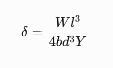
- d = central deflection (sag) of the beam
- W = applied load
- l = distance between the knife edges
- b = breadth of the beam
- d = depth (thickness) of the beam
- Y = Young's modulus of the beam material
Rearranging the above equation, Young's modulus is obtained as:
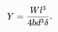
Substituting the weight of the load,
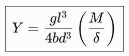
The term d/M represents the slope of the graph of mass (M) versus central deflection (d).
Therefore, Young's modulus can be determined directly from the slope of the M-d graph.
Thus, by measuring the dimensions of the beam and the corresponding central deflection for a known load, the Young's modulus of the material can be determined. The experiment demonstrates the relationship between the stiffness of a material and the amount by which it bends under an applied load, forming the basis for the design and analysis of structural members in engineering.
Apparatus Required
Section 03Apparatus
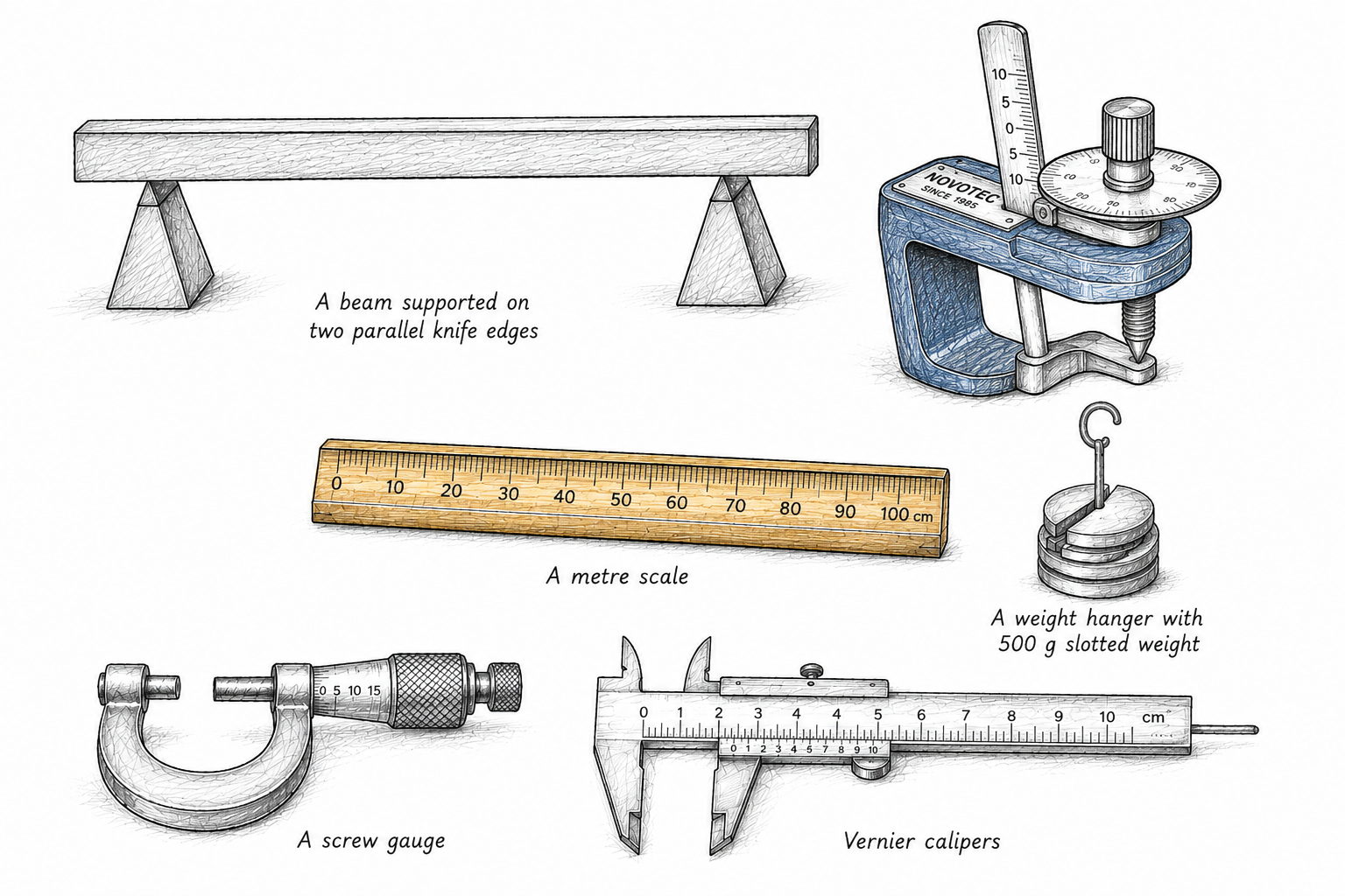
- A beam supported on two parallel knife edges
- A weight hanger (hook)
- 500 g slotted weights
- A metre scale
- A spherometer
- A screw gauge
- Vernier calipers
Procedure
Section 04Procedure (Real Experiment)
- Measure the distance l between the two knife-edge supports using a meter scale.
- Determine the least count and zero error (if any) of the screw gauge.
- Using the screw gauge, measure the depth (thickness), d, of the beam.
- Determine the least count and zero error (if any) of the Vernier calipers.
- Using the Vernier calipers, measure the breadth, b, of the beam.
- Determine the least count of the spherometer.
- Suspend the weight hanger, with the graduated scale attached, at the midpoint of the beam. Rotate the spherometer until its central screw just touches the upper surface of the beam. A thin paper strip may be used to detect the point of contact. Record the initial spherometer reading corresponding to zero applied load.
- Place a 500 g slotted weight on the hanger. The beam bends downward, creating a gap between the beam and the spherometer. Rotate the spherometer until it just touches the beam again and record the new reading.
- Increase the load in steps of 500 g up to 2500 g. At each load, adjust the spherometer until it just touches the beam and record the corresponding reading.
- After reaching 2500 g, begin unloading the beam. Record the spherometer reading at 2500 g during the decreasing-load cycle.
- Remove 500 g from the hanger. Rotate the spherometer in the opposite direction until it just touches the beam again, and record the reading corresponding to 2000 g.
- Continue decreasing the load in steps of 500 g until all the weights are removed. Record the spherometer reading at each load during the unloading process.
- For each load, calculate the mean spherometer reading by averaging the readings obtained during the loading and unloading cycles.
- Determine the relative depression (d) for each load by subtracting the mean reading at zero load from the corresponding mean reading.
- Calculate the depression produced by a 1500 g load using the differences between the following pairs of observations:
- 1st and 4th
- 2nd and 5th
- 3rd and 6th
Substitute the average value of depression into the formula to calculate Young's modulus (Y). - Plot a graph of applied mass (M) versus relative depression (d). Determine the slope of the graph, d/M, and use it to calculate Young's modulus from
Y = 4bd3gl3 / (d/M). - Compare the values of Young's modulus obtained from the calculation method and the graphical method, and report their average as the final value of the Young's modulus of the beam material.
Procedure (Virtual Experiment)
1. Measurement of the Thickness (d) of the Beam
- Open Simulation-I. A virtual screw gauge and the cross-section of the beam will be displayed.
- Determine the least count and zero error of the screw gauge.
- Open the screw-gauge jaws by dragging the thimble.
- Drag the beam towards the jaws of the screw gauge and release it.
- Close the jaws gently until they just touch the beam, and note the screw-gauge reading.
- Repeat the measurement 3-4 times at different positions of the beam.
- Record all observations in the Observation Table: Measurement of Thickness (d) of the Beam.
- Apply the required zero-error correction and calculate the mean thickness (d) of the beam.
2. Measurement of the Breadth (b) of the Beam
- Open Simulation-II. A virtual Vernier caliper and the cross-section of the beam will be displayed.
- Determine the least count and zero error of the Vernier caliper.
- Open the Vernier caliper jaws by dragging the Vernier scale.
- Drag the beam towards the jaws of the Vernier caliper and release it.
- Close the jaws gently until they just touch the beam, and note the Vernier-caliper reading.
- Repeat the measurement 3-4 times at different positions of the beam.
- Record all observations in the Observation Table: Measurement of Breadth (b) of the Beam.
- Apply the required zero-error correction and calculate the mean breadth (b) of the beam.
3. Measurement of Depression (d) for Different Loads
- Open Simulation-III. The experimental setup consists of a beam supported on two sharp, narrow knife edges, with a load hanger attached at the centre of the beam.
- The effective length (l) of the beam between the two knife edges is fixed at 1 m.
- Two sliders are provided: Load Slider to adjust the mass suspended from the hanger and Screw Gauge Slider to operate the screw gauge/spherometer used to measure the depression of the beam.
- Using the Load Slider, increase the load on the hanger in steps of 500 g, starting from 500 g and continuing up to 2500 g.
- For each load, use the Screw Gauge Slider to rotate the spherometer gradually until it just touches the beam.
- Note the spherometer reading at this position. The reading gives the depression (d) of the beam for the corresponding load.
- Repeat the measurements while decreasing the load in the same steps and record the corresponding depression readings.
- Enter all observations in the Observation Table for the beam measurements.
- Use the recorded data to analyze the relationship between load and beam response in the Result and Analysis section.
- Plot the required graph and determine the relevant experimental result from the graph and observations.
Simulation
SimulationObservation Table
Section 06Table 1: Thickness of Beam
Table 2: Breadth of Beam
Table 3: Depression of Beam for Different Loads
Result and Analysis
Section 07Result summary
The graph of mass versus relative depression is shown below. Use the slope of the plotted line to calculate Young's modulus of the beam material.
Calculation on freehandTool
Y = 4bd3gl3 / (d/M)